XRSProcessTool User Guide
X-ray Raman Scattering (XRS) data processing tool Version: 1.0 | Screenshots included
1. Introduction
XRSProcessTool is a desktop application for processing XRS experimental data from the B5 beamline. Key features:
- Load elastic-peak scan data and XRS scan data (
.nxsformat) - Display/adjust ROIs (crystal regions of interest) on the 2D detector images
- Fit each ROI's elastic peak with a Lorentzian and reject poorly fitted crystals
- Compute momentum transfer q and filter ROIs by q range
- Interpolate and sum spectra from multiple scans and ROIs to produce the final energy-transfer spectrum
- Save results as
.txttext files
Both single-detector (det2D) and dual-detector (lambda + minipix) modes are supported. The application starts in dual-detector mode by default.
2. Startup and Layout
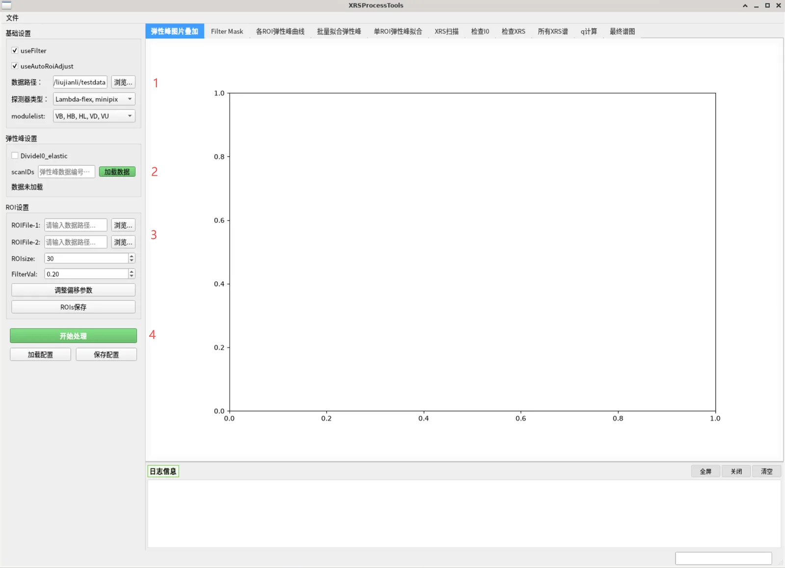
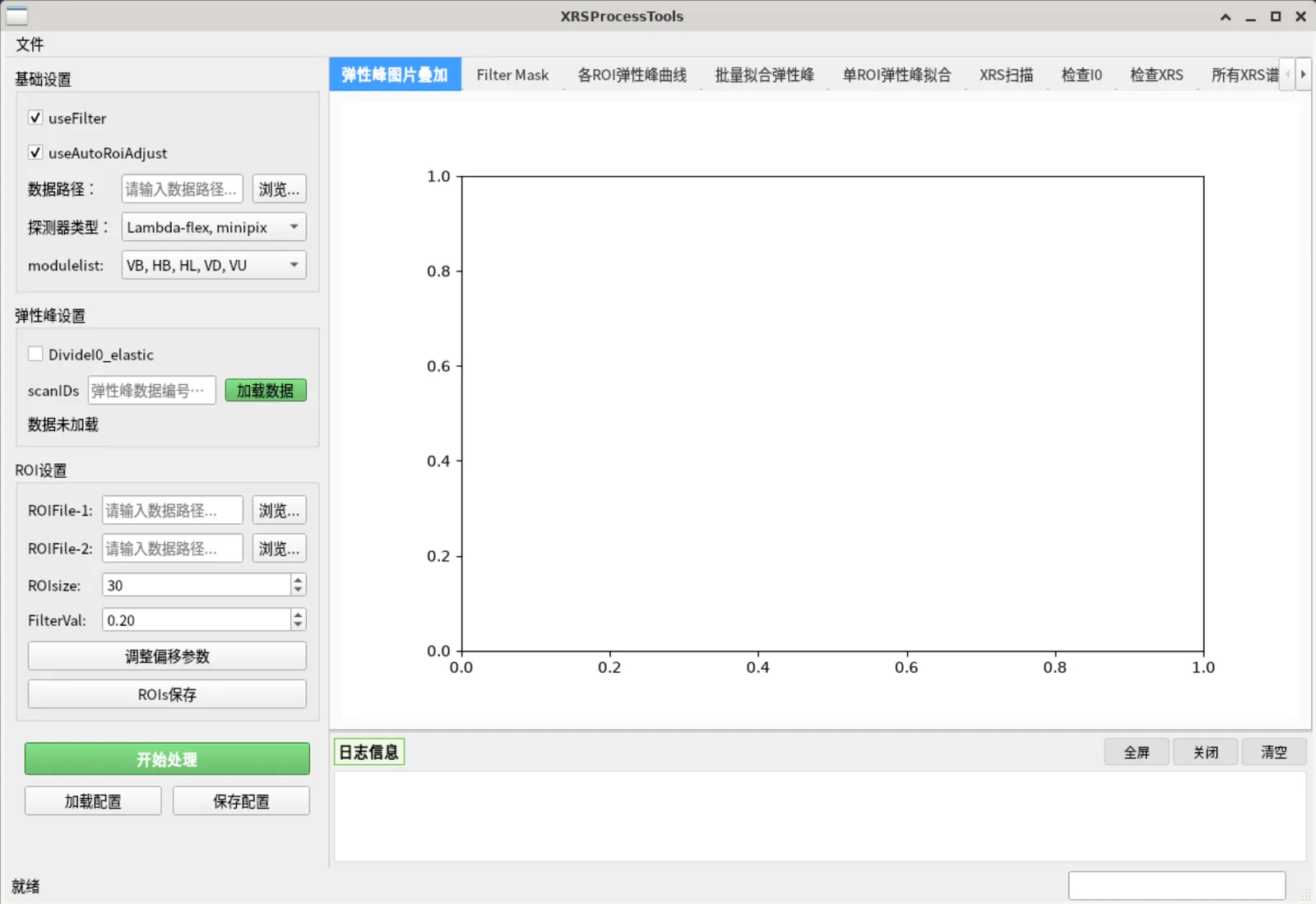
After launching XRSProcessTool, the main window is divided into three regions:
| Region | Description |
|---|---|
| Left panel | Parameter settings, organized into groups (Basic Settings, Elastic Peak Settings, ROI Settings, Fitting Settings, XRS Scan Settings, Final Spectrum, etc.). Relevant groups show/hide automatically as the right-side tabs switch. |
| Upper right | Tab area with 11 tabs, left to right in the order of the processing workflow. |
| Lower right | Log panel recording operations and errors (can be cleared). |
| Bottom status bar | Progress bar. |
Top menu bar: File → Save Results / Exit, View → toggle the left parameter panel / log panel, Language → 中文 / English.
3. Core Logic (read this first)
1. The "Process" button only processes the current tab
"Process" will NOT run the whole workflow automatically. It only executes the processing step for the currently selected right-side tab. Therefore the full workflow must be run manually, tab by tab from left to right.
While a tab is processing, the button turns red and shows "Processing" and is disabled; it turns green again when done.
2. Both panels load data by picking files directly
- Elastic Peak Settings → "Browse...": pick a single
.nxsfile (used for ROI localization and elastic peak fitting); it is read immediately and a content summary pops up - XRS Scan Settings → "Browse...": pick one or more
.nxsfiles; each file is read as it is picked. The load summary of every file goes to the log panel, and the status label shows the total number of loaded files plus the scan numbers of all loaded files (the leading digits of each file name). "Clear" removes all loaded XRS data
Both must be loaded — neither is optional. After changing parameters (I0 normalization, I0 PV, glitch removal), pick files again with "Browse..." or click "Process" on tab 5: files are re-read with the new settings, while files whose parameters did not change are not read again.
3. Data reuse
Loaded data stays in memory and is reused by subsequent tabs; there is no need to reload. After changing left-panel parameters, click "Process" on the corresponding tab again for the changes to take effect.
4. Data Preparation
The default data root directory is F:/Beamlines/B5/XRSdataProcessing/data, with the following structure:
data/
├── raw/                 # raw scan data
│   └── 11050_scan_20260414205302_1/
│       └── 11050_scan_20260414205302_1.nxs   # one folder per scan, containing the .nxs of the same name
└── processed/           # output directory for processed results
- Raw data: under
raw/, laid out as<scanID>_scan_<timestamp>_<index>/<same name>.nxs - The Data Path points at the data root (e.g.
.../data);rawis not appended to it. The file dialog opens at that directory, from which you enterraw/and pick the.nxsfiles; processed results are written toprocessed/under it. - If the data path is empty, it is inferred from the selected file and filled in (a path you have already set is never overwritten).
- ROI files: tab-separated
.txt, one crystal per row, columnsroi_label, x1, x2, y1, y2, x_shift, y_shift, x_expand, y_expand. Example ROI files are bundled underXRSProcess/ROI/(e.g.roi_60crystals-v3.txt,roi_minipix-v3-2.txt).
ROI file example (first few lines):
roi_label  x1  x2  y1  y2  x_shift  y_shift  x_expand  y_expand
VB-A1      35  66   3  31    0         0         0         0
VB-A2     112 144  57  86    0         0         0         0
5. Full Workflow
The following steps are ordered as recommended. Main line:
Set basic parameters → load elastic-peak data → (tabs 0–4) ROI localization & fitting → load XRS data → (tabs 5–8) XRS checks → (tabs 9–10) q calculation & final spectrum → save results
Step 0: Basic Settings (Basic Settings group)
In the left "Basic Settings" group:
| Parameter | Description | Default |
|---|---|---|
useFilter |
Use pixels above an intensity threshold inside the ROI box as a mask for extracting data (recommended) | ✅ |
useAutoRoiAdjust |
Auto-adjust ROI box position/size to the brightest pixels (recommended) | ✅ |
| Data Path | Data root directory (points to the data folder) |
…/data |
| Detector Type | Lambda-flex (single) / Lambda-flex, minipix (dual) / Lambda-flex-2, minipix (dual) |
dual |
| modulelist | Which modules to use: VB,HB,HL,VD or VB,HB,HL,VD,VU |
includes VU |
Step 1: Load Elastic-Peak Data (Elastic Peak Settings group)
- Click "Browse..." and pick the elastic-peak
.nxsfile (single file only) - The file is read immediately, a content summary dialog pops up, and the status label turns green with "Data loaded:
" - To normalize by I0, check
DivideI0_elasticfirst, then click "Browse..." and pick the same file again (picking the same file twice is allowed)
Step 2: ROI Settings (ROI Settings group)
| Control | Description |
|---|---|
ROIFile-1 Browse |
Select the main detector ROI file (required) |
ROIFile-2 Browse |
Select the second detector (minipix) ROI file (shown in dual-detector mode, required) |
ROIsize |
Pixel side length of the ROI box during auto-adjust (10–100, default 30) |
FilterVal |
Filter threshold (0–1, default 0.2): only pixels with intensity above FilterVal × max intensity inside the ROI are counted |
| Adjust Offsets | Opens a dialog to set x/y offsets for each module (VB/HB/HL/VD/VU/ROI2) for alignment |
Save ROIs |
Export the ROI geometries adjusted in tab 0 to a new file |
Tab 0: Elastic Peak Images
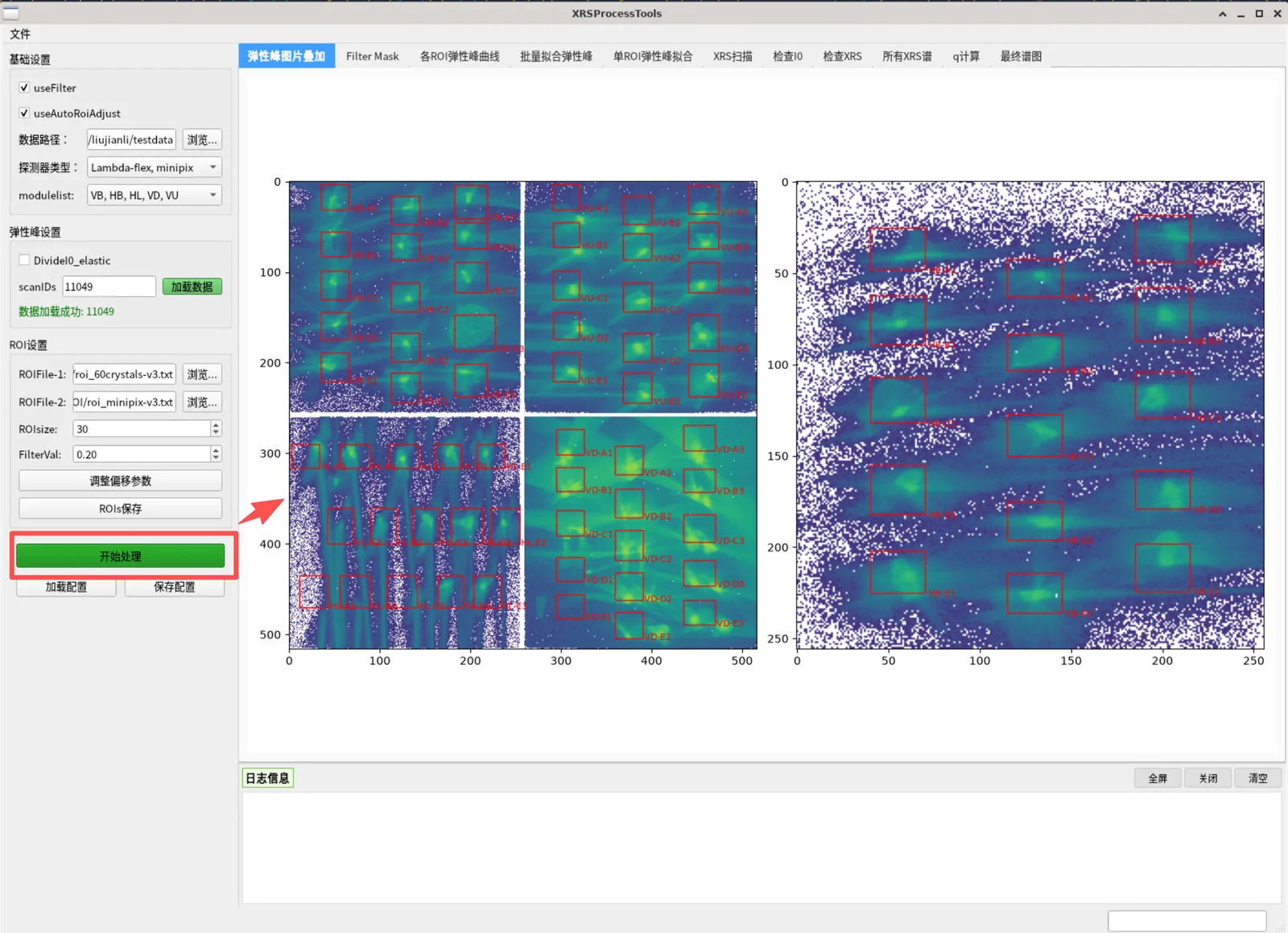
The first visualization step. Select this tab and click "Process" to show the elastic-peak scan's 2D detector image (log-scale overlay) with red ROI boxes and labels overlaid. In dual-detector mode, one image is shown per detector (lambda / minipix), side by side.
- ROIs are interactive: drag an ROI box directly on the image to reposition it
- After adjusting, use "Save ROIs" to export the updated ROI file
Tab 1: Filter Mask
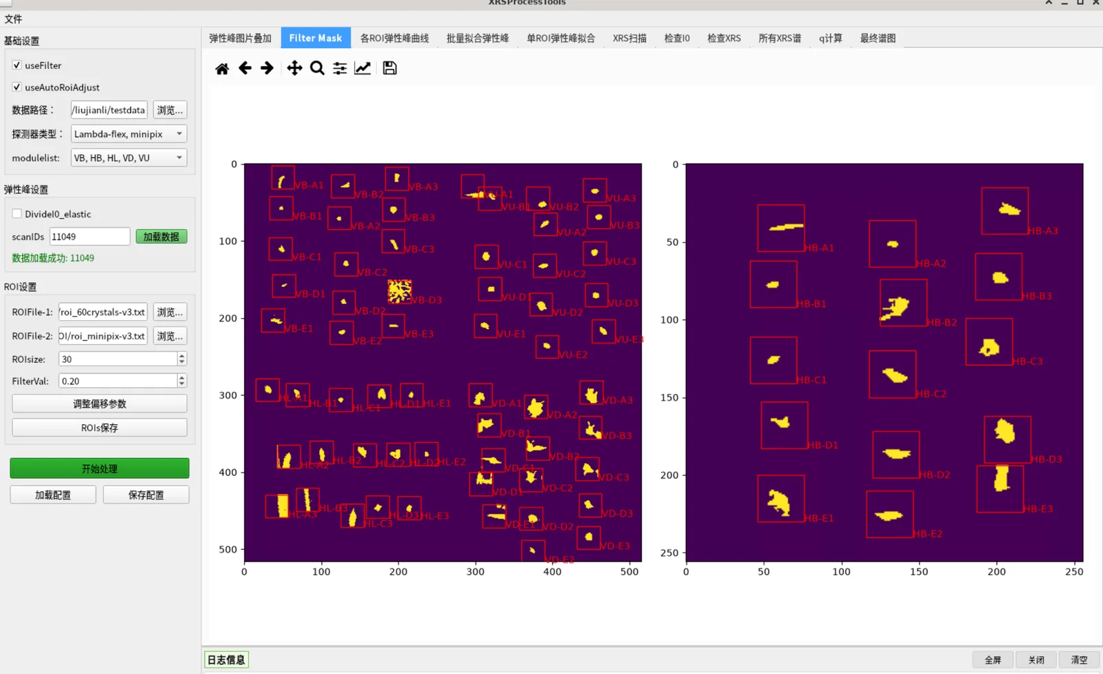
Shows the filter mask (pixels above the FilterVal threshold) overlaid, again with ROI boxes. If useAutoRoiAdjust is checked, ROIs automatically center on the brightest pixels and resize to ROIsize.
- Use this page to check mask quality; adjust
FilterValorROIsizeup/down and reprocess if needed
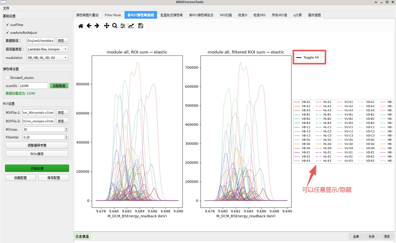
Tab 2: ROI Elastic Peak Curves
Shows each ROI's elastic-peak curve: left plot is the raw ROI sum, right plot is the filtered sum.
Interactions:
- Hover a curve → highlight red and bold
- Click a legend line → toggle that curve show/hide
- Click the "Toggle All" legend → show/hide all curves at once
Tab 3: Batch Fit Peaks
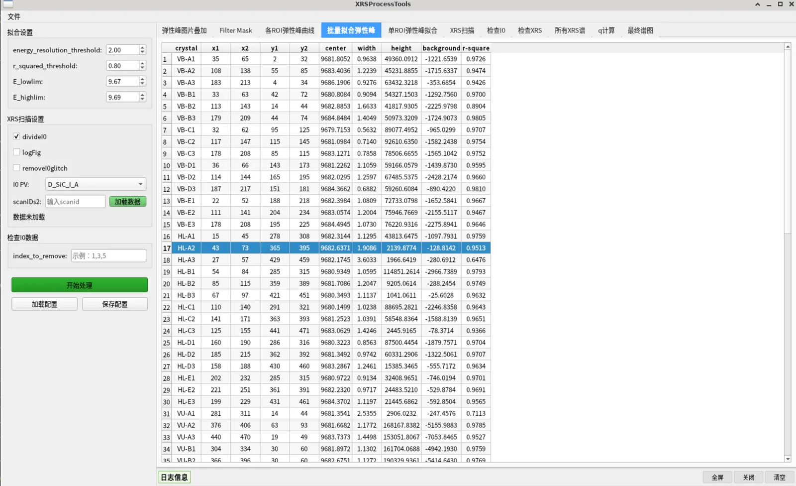
First set the thresholds in the "Fitting Settings" group:
| Parameter | Description | Default |
|---|---|---|
energy_resolution_threshold |
Energy-resolution threshold (eV); a FWHM exceeding it is marked as a bad fit | 2.0 |
r_squared_threshold |
Lower bound for fit R²; below it is a bad fit | 0.8 |
E_lowlim / E_highlim |
Reasonable elastic-peak center energy range (keV) | 9.67 / 9.69 |
Select this tab and click "Process". The software fits each ROI's elastic peak with a Lorentzian and displays the results in a table with columns: crystal, x1, x2, y1, y2, center[eV], width[eV], height, background, r-square, NumPixels.
- ROIs meeting any bad-fit criterion (R² too low, center out of range, negative amplitude, FWHM too large) are added to
BadFitListand automatically excluded from the final spectrum
Tab 4: Single ROI Fit
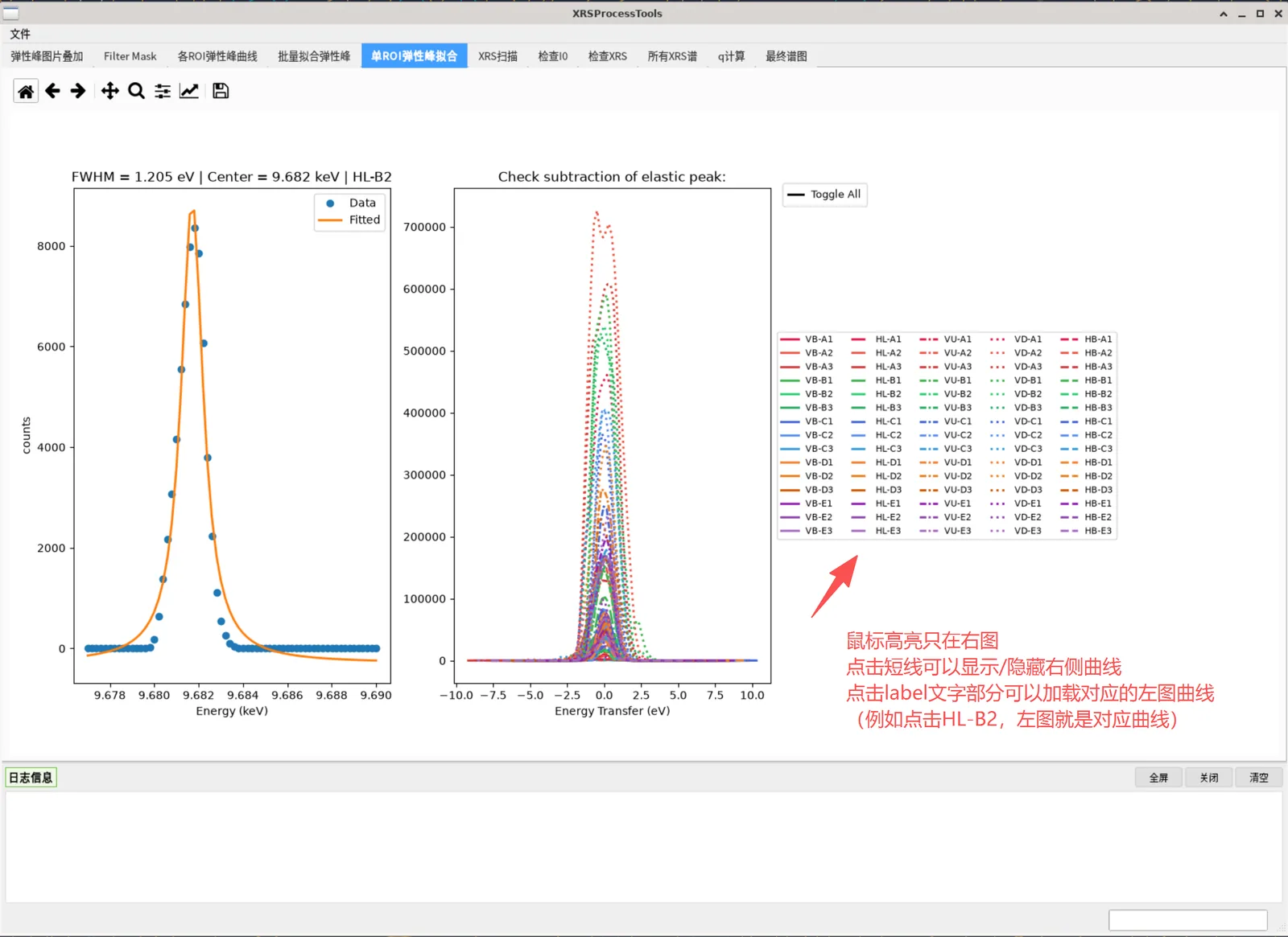
Used to inspect the fit quality of a single ROI. The left plot shows the data points and fitted curve of a crystal (with FWHM and center energy annotated); the right plot shows all ROI curves shifted so the elastic-peak energy is zero (energy-transfer view).
Step 3: Load XRS Data (XRS Scan Settings group)
- Click "Browse..." and multi-select the XRS
.nxsfiles. Each file is read as it is picked; files can be picked over several rounds, and picking an already loaded file does not read it again - For every file, a load summary is written to the log panel (scan number, file name, 2D data shapes, number of 1D channels, I0 channel, number of glitch points removed); the status label shows "N file(s) loaded:
, , …" listing every loaded file. Failed files are flagged in red - "Clear" empties all loaded XRS data (in-memory data and curves are reset)
- Settings:
divideI0: normalize by I0 (recommended)removeI0glitch: remove I0 glitch points (adjacent-point ratio < 0.7 treated as a glitch, replaced with the local mean)I0 PV: choose the I0 signal channel (D_SiC_I_A/D_QXBPM_I_Sum/D_QXBPM2_I_Sum)logFig: logarithmic plotting After changing these, pick files again with "Browse..." or click "Process" on tab 5 to re-read with the new settings (files whose parameters did not change are not read again)
Tab 5: XRS Scan
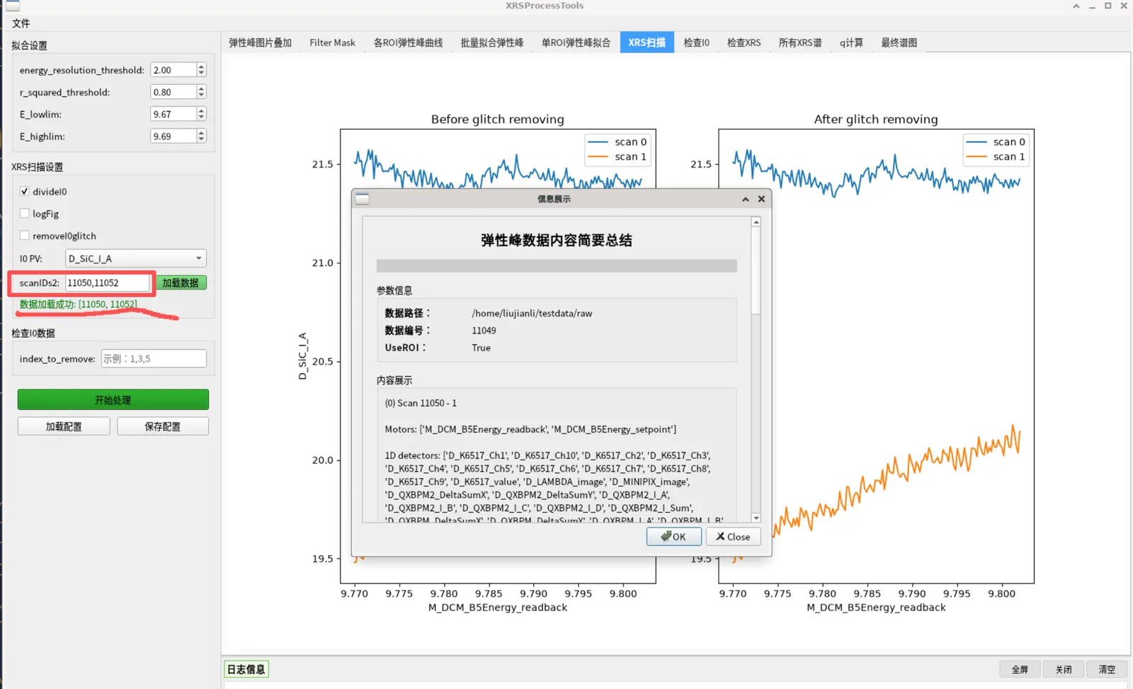
Select and click "Process" to show the I0-vs-energy curves (two subplots: before and after normalization + glitch removal), to confirm XRS data and I0 quality.
Tab 6: Check I0
In the "Check I0 Data" group's index_to_remove, enter scan indices to exclude (e.g. 1,3,5). After "Process", an I0 before/after removal comparison is shown, to pick out bad scans.
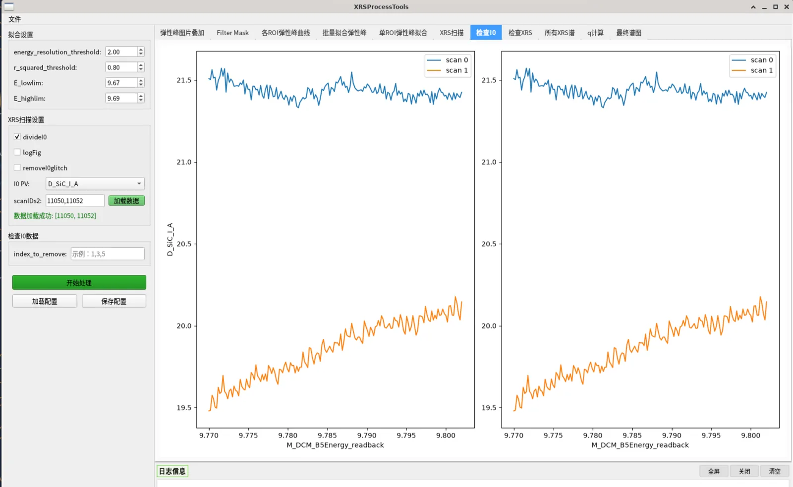
Tab 7: Check XRS
Shows the 2D stacked XRS detector image (log scale) with ROI boxes overlaid; one image per detector in dual mode. Used to check XRS image quality and ROI coverage.
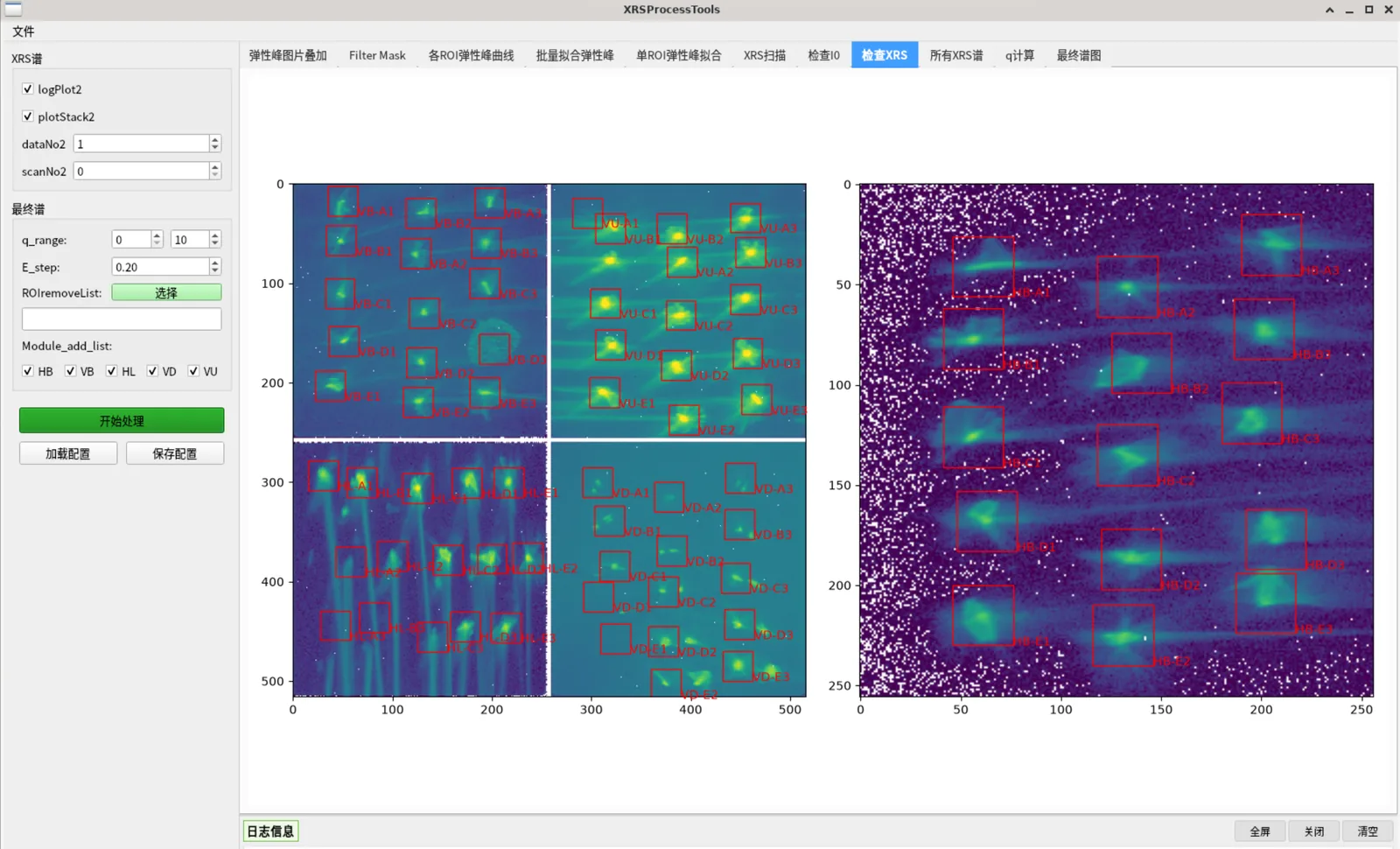
Tab 8: All XRS Spectra
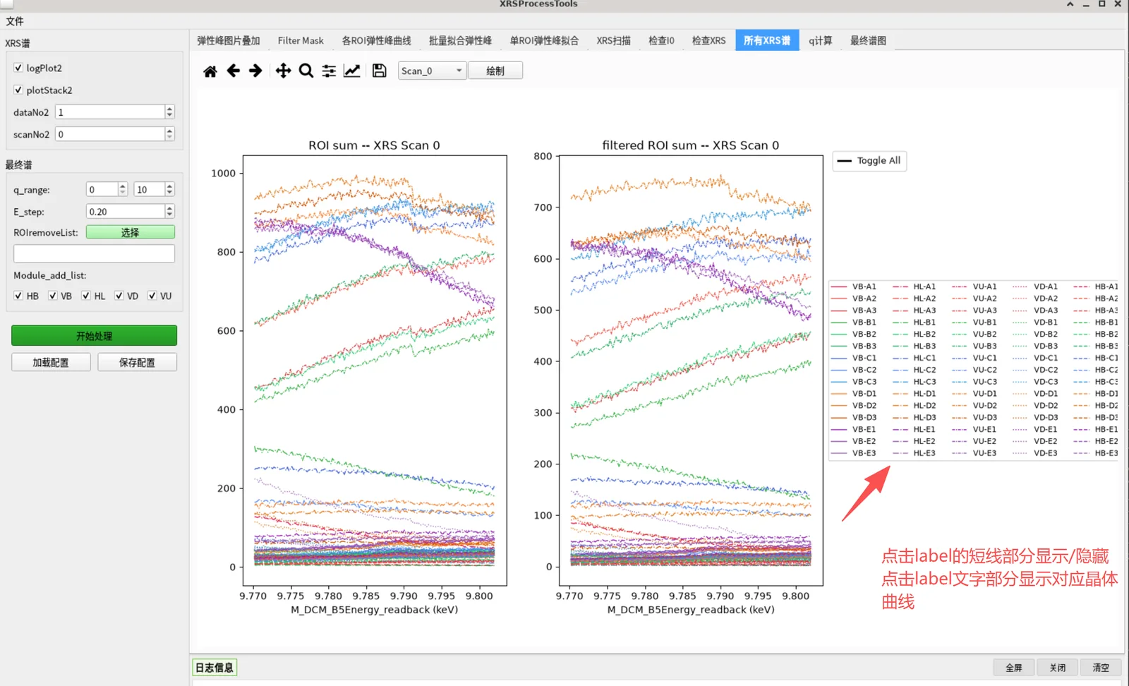
Shows the XRS spectra (raw vs filtered) for each scan and ROI.
- The top dropdown selects the scan number + a "Draw" button replots
- Hover to highlight; click a legend line to toggle visibility
- Click a legend label → switch to that crystal's single-spectrum view (left raw, right filtered, with scan number annotated); click "Toggle All" again to return to the overview
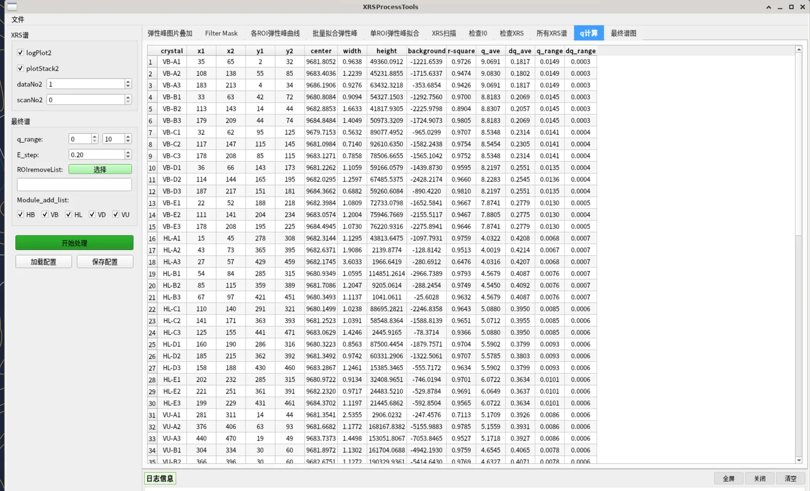
Tab 9: q Calculation
Click "Process" to compute each ROI's momentum transfer q (based on each module's fixed scattering angle and the elastic-peak energy), adding q_ave, dq_ave, q_range, dq_range columns to the table. This prepares the q filtering for the final spectrum.
Tab 10: Final Spectrum
In the "Final Spectrum" group, set the final-spectrum parameters:
| Parameter | Description | Default |
|---|---|---|
q_range |
Only sum ROIs whose q_ave falls in this range | 0–10 |
E_step |
Energy interpolation step (eV) | 0.2 |
ROIremoveList |
Manually excluded crystals (click "Select" to pick from the crystal grid) | empty |
Module_add_list |
Modules participating in the sum (HB/VB/HL/VD/VU checkboxes) | all |
Click "Process" to generate the final spectrum: the top plot is the summed total spectrum, the bottom shows subplots per scan (to check the elastic-energy subtraction is correct).
Toolbar buttons:
- Scan_N dropdown: select scan number
- Final Spectrum: show only the summed total spectrum
- Energy Transfer: show the energy-transfer subplot of the selected scan
In the final spectrum, an ROI is excluded if it meets any of: in ROIremoveList, in BadFitList, module not selected, or q outside q_range.
6. Save Results
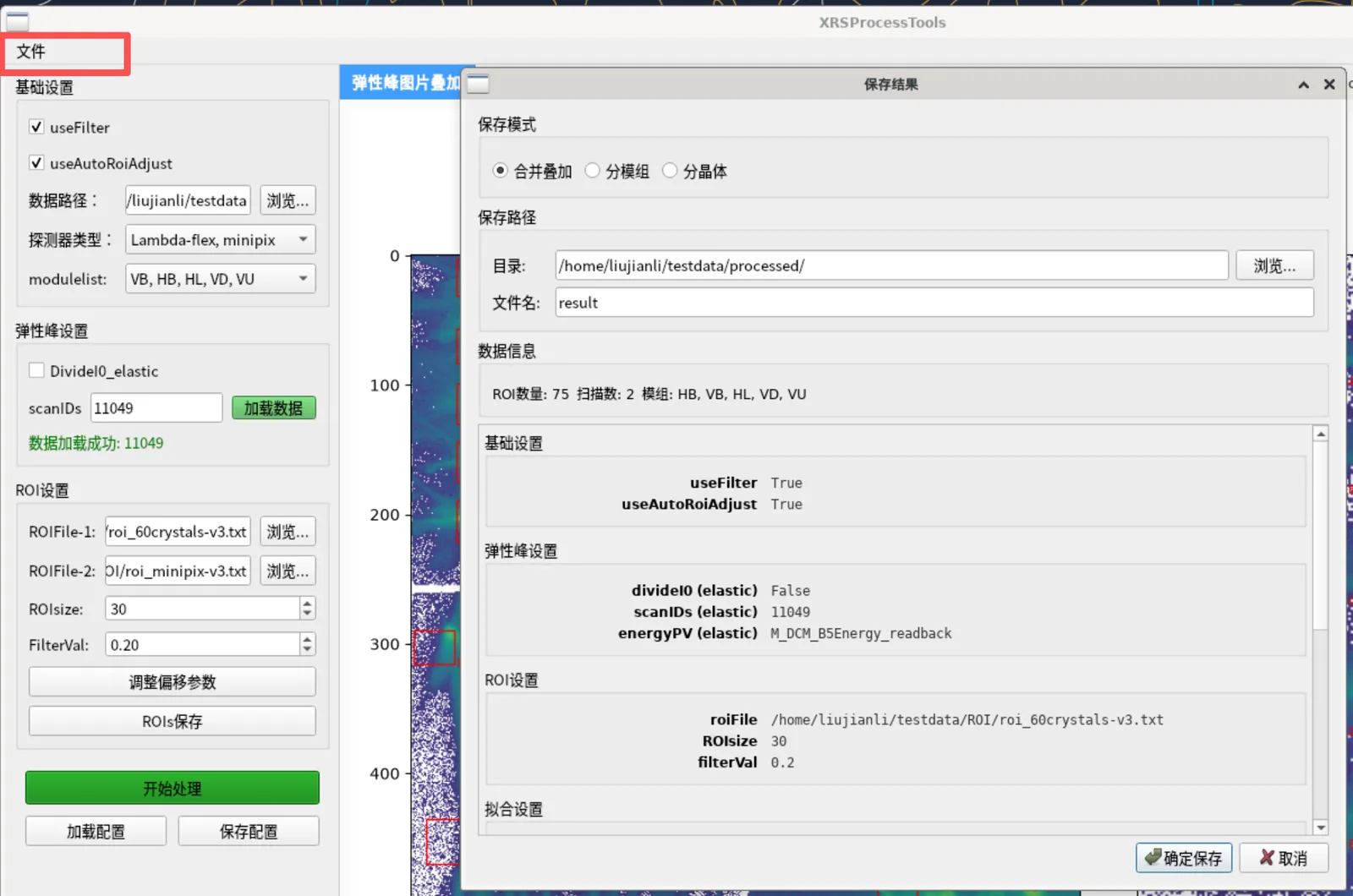
After processing, click File → Save Results to open the "Save Results" dialog:
Save Mode (choose one of three):
Mode Description Output files Merged (default) Sum all selected ROIs into one spectrum <filename>_data.txt(energy transfer + intensity)By Module One column per module, in the same file <filename>_data.txt(energy + module columns)By Crystal One file per crystal + a summary each <crystal>_data.txt+<filename>_all_data.txtAll three modes additionally output:
<filename>_rois.txt: fit results (fitResult)<filename>_info.txt: a record of all processing parameters this run
Save Path: directory defaults to
<data path>/processed/; the filename is used as the subfolder name (defaultresult)Confirm to save; a "Save Succeeded" prompt appears
Output files are tab-separated text. Example (_data.txt):
Energy Transfer (eV)  Intensity
90.2                  20.33
90.4                  18.41
…
7. Parameter Config Save & Load
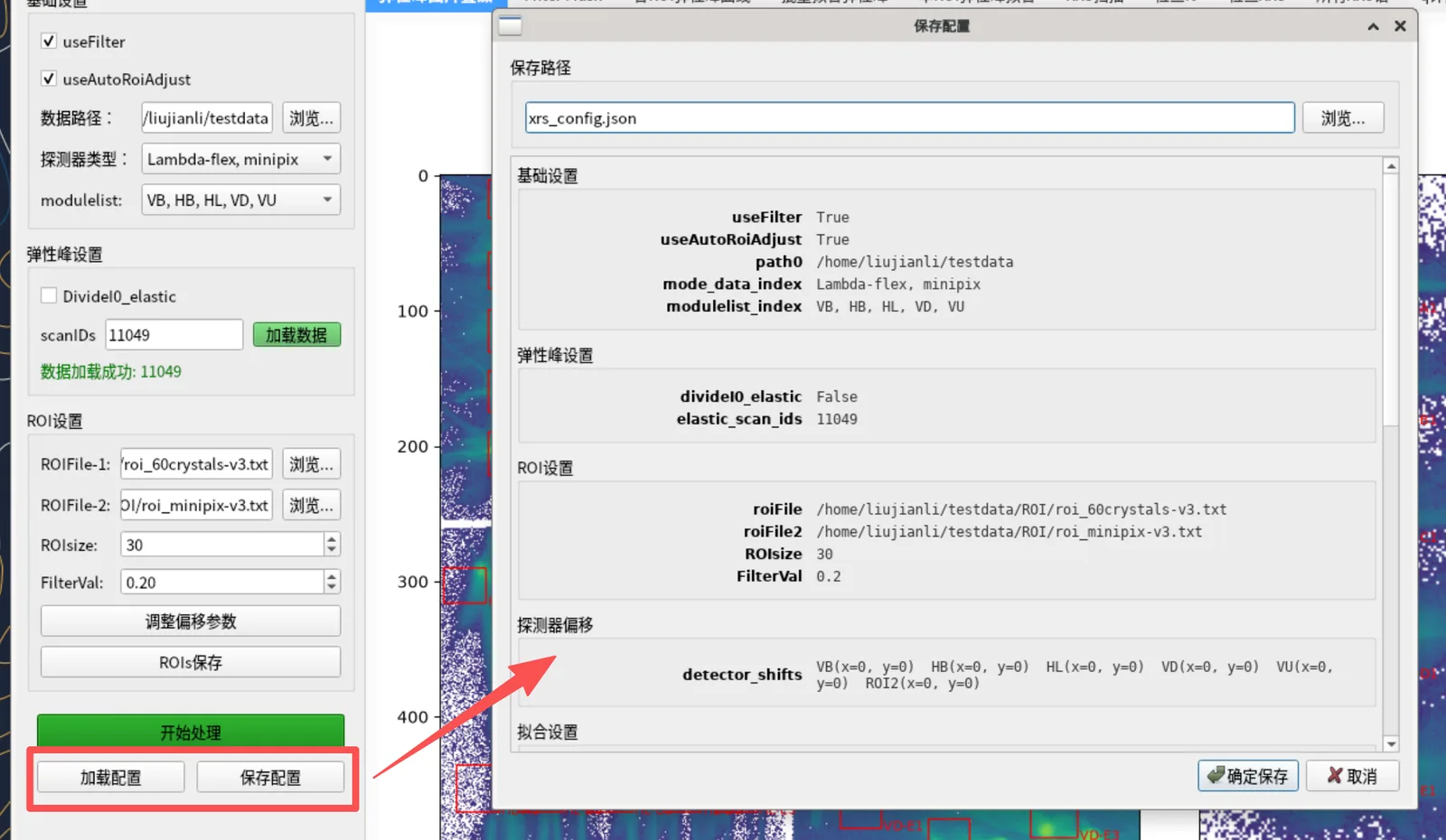
The "Load Config" and "Save Config" buttons at the bottom of the left panel save/load all parameters (including detector offsets, fitting thresholds, q range, etc.) as a .json file, for reuse without re-entering.
- Save Config: shows a parameter preview, choose a path to save as
.json - Load Config: choose a
.jsonfile; after validation, a preview is shown (errors in red, missing items in gray); confirm to apply to the UI
8. Quick Checklist
| Step | Action |
|---|---|
| 1 | Basic Settings: set data path, detector type, modules |
| 2 | Elastic Peak Settings: Browse and pick a single .nxs (auto-read) |
| 3 | ROI Settings: choose ROIFile-1 (dual mode adds ROIFile-2), set ROIsize/FilterVal, adjust offsets as needed |
| 4 | Tab 0 → Process → check/drag ROIs, Save ROIs as needed |
| 5 | Tab 1 → Process → check mask |
| 6 | Tab 2 → Process → check per-ROI elastic peaks |
| 7 | Fitting Settings: set thresholds |
| 8 | Tab 3 → Process → view fit table, note bad fits |
| 9 | Tab 4 → Process → spot-check single-ROI fit |
| 10 | XRS Scan Settings: Browse and pick .nxs files (multi-select, read one by one, summaries in the log) |
| 11 | Tab 5 → Process → check I0 |
| 12 | Check I0: enter index_to_remove → Tab 6 Process |
| 13 | Tab 7 → Process → check XRS 2D image |
| 14 | Tab 8 → Process → check all XRS spectra |
| 15 | Tab 9 → Process → view q table |
| 16 | Final Spectrum: set q_range / E_step / ROIremoveList / modules |
| 17 | Tab 10 → Process → view final spectrum |
| 18 | File → Save Results → choose mode/path → OK |
9. FAQ
Q: "Process" does nothing? A: Make sure a single elastic-peak file is selected and at least one XRS file has been picked (files are read as soon as you pick them; results are in the log panel), and that the correct tab is selected.
Q: A tab shows blank? A: Usually a missing prerequisite step. Process the tabs left to right, ensuring previous tabs have run "Process".
Q: Too few ROIs in the final spectrum?
A: Check BadFitList (tab 3 bad fits), ROIremoveList (manual exclusions), Module_add_list (unselected modules), q_range (q out of range). Loosen the fit thresholds or widen the q range to include more ROIs.
Q: Only one detector visible in dual mode? A: Confirm "Detector Type" is a dual-detector mode and ROIFile-2 has the minipix ROI file selected.
Q: Chinese shows as boxes?
A: The packaged build bundles the CJK font. Running from source requires a system CJK font (Linux: sudo dnf install google-noto-sans-cjk-sc-fonts).
Q: Some parameters are wrong after loading a config? A: Items marked red/gray in the load dialog are erroneous or missing and will use default values; correct the source config file as prompted.
This guide is updated with the software version. Contact the maintainer with any questions.